progressJanuary 2008
February 2008March 2008May 2008fileslinks |
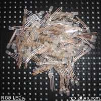
the RGB LED test circuit
2 MAX7219 are used to drive the RGB LED. 1 for the Red and Green LEDs, 1 for the Blue LEDs. They are connected in cascade. The current limiting resistor is set to 22k to limit the current to below 20mA. This is a safe current value for the LED.
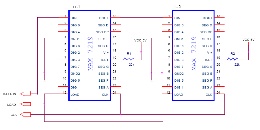
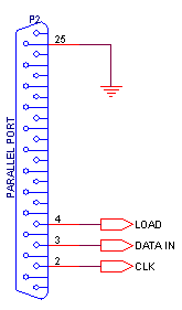
The DATA, CLK, and LOAD is connected to the parallel Port of the computer as shown. It is important to connect the ground of the circuit to ground of the parallel port (any of Pins 18-25), else the circuit would show unexpected outputs.
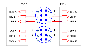
The cathodes(-) of Blue LEDs are given to DIG0 of MAX7219 IC 1, where as the cathodes of Red and Green are given to DIG0 of IC 2.
Software
The Visual C++ code written for driving the circuit with parallel port support dll's from logix4u.net is avaliable here
RGB LED LightShow...

| ||