MULTICOLOUR LED DISPLAY
Minor Project Report
Submitted in
partial fulfillment of the requirements
For the award of the degree of
Bachelor of Technology
In
Electronics and Communication Engineering
Of
COCHIN UNIVERSITY OF SCIENCE AND TECHNOLOGY
Submitted by
Aleena Emmanuel(02)
Arun Prabhakar(08)
Arvind G Shankar(10)
Raji James(30)

Department of
Electronics & Communication Engineering
Model Engineering
College
Kochi 682 021

GOVERNMENT MODEL ENGINEERING COLLEGE
THRIKKAKKARA
KOCHI
DEPARTMENT
OF ELECTRONICS AND COMMUNICATION
ENGINEERING
Cochin
University of Science and Technology
BONAFIDE CERTIFICATE
This is to certify that the mini project report
entitled
…………………..………………………………………………………………………
Submitted by
…………………..………………………………………………………………………
…………………..………………………………………………………………………
…………………..………………………………………………………………………
…………………..………………………………………………………………………
…………………..………………………………………………………………………
is a
bonafide account of the work done by him/her under our supervision.
|
Mrs.
Minimol M.G
Head of the Department
|
Mrs Anjana Devi
Project Guide
|
Mr Vinu Thomas
Project Coordinator
|
ACKNOWLEDGEMENT
At this moment of accomplishment, we are
presenting our work with great pride and pleasure, we would like to express our
sincere gratitude to all those who helped us in the successful completion of
our venture. First of all, we would like to thank our Principal Prof. Suresh Kumar P who provided us
with all facilities and amenities for the development of our project. We would
like to thank our HOD, Dr Mini M G for
helping us in the successful accomplishment of our project. We are exceedingly
grateful to our project coordinator Assistant Professor, Mr. Vinu Thomas for his
timely and valuable suggestions. We would also like to thank our project
guide Senior Lecturer Mrs.Anjana Devi who gave us constant
guidance and support throughout this journey of turbulence.
We also sincerely
thank Mr. Biju Mathew, Mrs. Geetha,
Lab Technicians, department of Electronics and Communication for their constant
support and encouragement for our project.
We would also
like to thank our parents and friends for their over whelming and whole hearted
encouragement and support without which this would not have been successful.
Above all we
thank God almighty for constantly motivating us with His love, and giving us
courage at each stride to step forward with confidence and self –belief.
ABSTRACT
LED's are a fantastic way to illuminate any kind of sign,
be it lettering or panels. LED Dot-Matrix Displays are a common sight
nowadays on streets, malls, buildings, parks and other public places. It is a
way of visual information where large LCD and other display become too much
expensive. The commonly seen displays are single coloured or having 2 or 3
colours .But here multicoloured LED display is being introduced .This project
provides an efficient and scalable approach to LED Dot Matrix displays.
The system is comprised of a tricolor dot matrix display panel
with an interface circuit to a computer. It also comprises an executive program
that runs on the computer for the display control of characters, decorative
pattern or messages on the display panel. A multicolour LED Indoor Advertising Display can be used by companies to advertise even in bright
day-light conditions. The display board displays any character
entered from the host computer which is interfaced using USB to a
microcontroller that initializes the led driver. The advantage of this project
is that size of the display board can be increased row wise and column wise
without making any changes in the circuitry since display board is the
repetition of a small independent module.
Contents
Chapter 1 Project
Overview.. 7
1.1
Introduction. 7
1.2
Objective. 8
1.3
Specifications. 8
Chapter 2 System Overview.. 9
2.1
Block Diagram.. 9
2.1.1 LED Matrix. 9
2.1.2 LED Driver. 10
2.1.3 Microcontroller. 10
2.1.4 Universal Serial Bus Interface. 10
2.2
Advantages and applications. 10
Chapter 3 Project Design. 12
3.1
LED Module. 12
3.1.1 LED Array. 12
3.1.2 LED Driver – MAX7219. 13
3.2.1 PIC18F4550. 17
3.2.2 20MHz Crystal oscillator. 19
3.2.3 USB 2.0. 19
3.2.4 USB Connector. 20
3.2.5 Push buttons "Reset" and
"Program". 20
3.2.6 Status
LEDs. 20
3.3
Power Supply. 22
3.3.1 Transformer. 23
3.3.2 Bridge rectifier. 23
3.3.3 Regulator IC 7805. 23
3.3.4 Power Transistor 2n2955. 24
3.4
Circuit 24
Chapter 4 PCB Design. 25
4.1
LED Array. 25
4.2
LED DRIVER CIRCUIT. 26
4.3 USB INTERFACE. 27
Chapter 5 Software. 28
5.1
Flow Charts. 28
5.1.1 Software Flow.. 28
5.1.2 Firmware Flow.. 28
5.2
Source Codes. 29
5.2.1 Software Code. 29
5.2.2 Firmware Code. 32
Chapter 6 Conclusion. 36
6.1
Observations. 36
6.2
Future Scope. 36
Bibliography. 37
Appendix. 38
APPENDIX
A – Cost Report 38
APPENDIX
B – Datasheets. 38
List of Figures
Figure 1 Block Diagram.. 9
Figure 2 RGB LED Pinout. 12
Figure 3 MAX7219 Pinout. 13
Figure 4 RSET vs. Segment Current and LED Forward Voltage. 14
Figure 5 Led Driver Circuit. 15
Figure 6 Led Array. 16
Figure 7 PIC18F4550 Pin
out. 18
Figure 8 USB Pin
Description. 19
Figure 9 USB CONNECTOR. 20
Figure 10 State LED Status. 21
Figure 11 Schematic of the USB
interface. 21
Figure 12 SCHEMATIC OF LED DRIVER
WITH PIC. 22
Figure 13 Basic block diagram of
power supply. 22
Figure 14 7805 Pinout. 24
Figure 15 Power Supply
Circuit. 24
Figure 16 LED PCB. 26
Figure 17 MAX7219 PCB. 26
Figure 18 Microcontroller
PCB. 27
Figure 19 Cost Report. 38
Visual impact is the most effective mode of influencing
human minds which is the main aim of adverstisements etc. A display device
serves this purpose.A display device
is a device for presentation of information for visual or tactile reception, acquired, stored,
or transmitted in various forms. The display devices used to display information on machines, clocks, railway
departure indicators and many other devices require a simple display of limited
resolution. The display consists of a matrix of lights or mechanical indicators arranged in a
rectangular configuration (other shapes are also possible, although not common)
such that by switching on or off selected lights, text or graphics can be
displayed. Various modifications has been made in the display board.
Now LED display panels are widely used throughout the world in
all situations to create images for visual displays in a variety of applications
including communication and visual display devices. LED array display board is
a popular instrument for commercial usage. Many banks, shops and cinemas are
willing to install one piece of it because of its versatility. LED array
display board can be very bright and eye-catching. Display signs used for
advertising or for displaying direction or other information to motorists have
an important feature in common. They should be eye-catching and their
information should be easy to absorb. In advertising, a signboard made of an
LED display generally standing at a conspicuous location, such as a bustling
road, is widely used. The LED display comprises a plurality of LEDs controlled
by special hardware and software to perform moving images on a screen thereof
to attract the attention of passersby. The LED array display board is used in a
bank to show the current stock market value, currency exchange rate and
interests rate. It can also be used in a shop to tell people the prices and
other commercial information. LED display board serves the above purposes with
advantages rendered by LEDs
- LEDs produce more
light per watt than incandescent bulbs; this is useful in battery powered
or energy-saving devices.
- LEDs can emit light
of an intended color without the use of color filters that traditional
lighting methods require. This is more efficient and can lower initial
costs.
- The solid package of
the LED can be designed to focus its light. Incandescent and fluorescent
sources often require an external reflector to collect light and direct it
in a usable manner.
- LEDs are
ideal for use in applications that are subject to frequent on-off cycling,
unlike fluorescent lamps that burn out more quickly when cycled
frequently, or HID lamps that require a long time before restarting.
- LEDs,
being solid state components, are difficult to damage with external shock.
Fluorescent and incandescent bulbs are easily broken if dropped on the
ground.
- LEDs can
have a relatively long useful life.
- LEDs
light up very quickly’
- LEDs can
be very small and are easily populated onto printed circuit boards.
Organic light emitting diodes (OLED) are a promising
technology for flat-panel displays. Owing to high brightness, fast response
speed, light weight, thin and small features, full color, no viewing angle
differences, no need for an LCD back-light board and low electrical consumption, an
organic light emitting diode display takes the lead to substitute a twist nomadic
(TN), a super twist nomadic (STN) liquid crystal display, or a small-sized
thin-film transistor (TFT) LCD
display. Light emitting diodes are
useful in a wide range of high and low resolution display devices.
Display technology pervades all aspects of present day life,
from televisions to automobile dashboards to laptop computers to digital
cameras. Single coloured LED display
boards are very common nowadays. The same yellow or red coloured board is not
attractive .The introduction of multicoloured LEDs into the display boards make
them attractive. This project is oriented towards the
development of a prototype of a multicoloured LED display board which is being
controlled by an LED driver. The use of multicolour LED opens door to many
applications. The display board is made on readily available components. The
important requirement is that the display board should have long life expectancy, high
tolerance to humidity, low power consumption and minimal heat generation. The
fundamental part is a 4X4 LED module which could be repeated column wise or row
wise to enlarge the display without any change in circuitry. Both single line
and double line display could be affected. Motivation towards the project was
to make available a readily expandable multicolour display board which can be
used for multiple purposes.
- 4 x 4 multicoloured LED modules (8)
- USB interface
- High speed response
- Power supply requirement :5V ,4A
A
simplified block diagram is given below.
A 4X4 LED module is the
fundamental part of the display. LED display panels use matrix addressing
techniques to organize the light emitting elements or pixels into a number of
rows and columns with each pixel at an intersection of a particular row and a
particular column. A light emitting device (LED) display is typically supplied
with data addressed from graphical memory location in accordance with a
column-major display. The LED display illuminates pixels on a column basis by
providing sourcing and sinking currents to diodes in the display. An LED
display is typically made up of various dots arranged in a matrix pattern
having rows and columns. The dots are usually called pixels where the pixels
are made up of several LEDs. Illuminating the pixel requires activating an
intersecting row and column thereby providing a closed current path that
includes the pixel to be illuminated.
The individual
LEDs emit light of three basic colours: red, green and blue. Typically, each
pixel is composed of at least one LED of each colour. In LED displays, one dot
is formed by utilizing a plurality of cannon ball-shaped LED lamps each having
different luminescent colours. The intensity of the LEDs is usually controlled
by controlling the current to the individual LEDs. This is done by means of a
led driver. A pixel can produce a specific perceived colour by varying the
drive to the three colours of LEDs that comprise the pixel. By controlling the
current drive to each of the LEDs that makes up a pixel and in turn controlling
each of the pixels that make up a matrix of pixels, an LED display device is
capable of displaying a plurality of colours and light intensities so as to
realize, for example, a multi-colour display. As the resolution of displays
increases, the number of pixels in each row and column also increases and the
amount of time available to illuminate each pixel decreases. As the
illumination time decreases, each pixel must be driven with a larger current to
provide a pixel intensity that maintains acceptable image intensity and viewing
characteristics.
Light Emitting Diode:
Multicolour LEDs are used to provide colourful display. They primarily
provide three colours: red, green, and blue. By the combination of these
colours in correct proportion many varieties of colour are possible. The three
colours could be individually controlled as controlling three single LEDs.
The control of the LED display module is done by means of
LED driver. It is programmable using microcontroller. An LED Driver has a shift register embedded that will take
data in serial format and transfer it to parallel. It performs following
functions:
o
It controls the intensity and brightness of the display
o
It controls the colour of the display
o
It decides which led is to be lighted to display specific
character
o
It receives the input signal specifying the character to be
displayed from the microcontroller which is controlled by host computer using
USB interface.
The character to be displayed is inputted from
the host computer using USB interface. PIC18F4550 is used to provide the USB
interface to the LED driver which controls the display. The PIC is programmed
such that it provides USB interface. A self programmable PIC is used.
It provides the communication between the host computer and
display board. It also can provide power supply for the microcontroller.
Advantages:
° No
More Monotonous Same Advertisement again and again for days/months. (message to
be displayed can be changed instantaneously)
° Instant,
Current and Hot Topics reach the Public immediately.
° Common
Display system which displays instant messages like Flash News, in
Places like
exhibitions, Road side Hoardings.
° Instant
Message Delivery.
° Easy
to change messages.
° Attractive
multicolour display.
° A
high density display board could be used for video display.
° Eye
catching display serving the purpose of advertisements.
° Media
for indoor & outdoor advertising and are clearly visible from very long
distance.
Applications:
° Advertisement
Hoardings with dynamic update of Flash News.
° Instant
update of Petrol Prices to all petrol Bunks from a Central office.
° Stock
Tickers, which displays dynamically current value of the Stocks and the
trend.
° Current
Prices of Commodities at different parts of the country.
° Shopping
malls & retail stores.
° Railway
information.
° Amusement
Parks & Zoo's.
° Traffic
Information.
°
Pedestrian countdown system for maximum
pedestrian safety.
Hardware requirements:
o
4 x 4
LED array
o
LED
driver MAX 7219
o
Resistors
– 22 KΩ, 15 KΩ
o
Capacitor
0.01μF
It consists of 16 multicoloured LEDs arranged in 4x4 matrix format. The
LED used is LED 339-1VRKGBBW-1 from ever bright. It is a multicoloured common
cathode led with 2 Blue LEDs, 1 Green and 1 Red LED. It
has 6 pins: 2 Blue Anodes & their common cathode, 1 Green and 1 Red anode
& their common cathode. Blue LEDs have lower brightness
compared to Red/Green, so there are 2 Blue LEDs in this package. Multicolour LED provides primarily blue,
green, yellow colour by giving bias to appropriate pins.
 Specifications:
If (typical
forward current): 20mA
Cut in Voltage
Red: 1.6V
Green: 1.8V
Blue: 2.5V
Figure
2 RGB LED Pinout
Also by varying the current to various pins
a variety of colours can be obtained. The red, blue, green anode lines are
connected in horizontal lines while cathode lines in vertical lines. Since the
LEDs are arranged in matrix format each LED could be controlled individually.
LED driver used is MAX7219. It can drive 64
single LEDs. The 7219 can source up to 40mA and control an 8x8 single LED
matrix. (Here 2 MAX7219 is used to control a 4X4 matrix). Individual LEDs can
be turned on or off with 3 wire serial interface (CLK, DATA, LOAD). 16 Brightness
steps are also provided, which can control the brightness of all the 64 LEDs.
Thus it provides both software and hardware control of brightness. It drives
common cathode LED display. It provides 100MHz serial interface.
The LED
driver has a 16 bit shift register. Input signals are CLK, DIN, and LOAD.
Serial data at DIN, sent in 16-bit packets, is shifted into the internal 16-bit
shift register with each rising edge of CLK regardless of the state of LOAD.
The data is then latched into either the digit or control registers on the
rising edge of LOAD/CS. LOAD/CS must go high concurrently with or after the
16th rising clock edge, but before the next rising clock edge or data will be
lost. Data at DIN is propagated through the shift register and appears at DOUT
16. 5 clock cycles later. Data is clocked out on the falling edge of CLK.
Figure 3 MAX7219 Pinout
Specifications:
Operating Supply Voltage: 5V
Shutdown Supply Current: 150μA
Operating Supply Current: 330 mA
ISEG : -40mA
Resistor
(RSET)
The MAX7219 allows display brightness to be controlled with an
external resistor (RSET) connected between V+ and ISET. It is used to set the
peak segment current. The peak current sourced from the segment drivers is
nominally 100 times the current entering ISET. Its minimum value should be
9.53kΩ, which typically sets the segment current at 40mA. Display
brightness can also be controlled digitally by using the intensity register. Digital
control of display brightness is provided by an internal pulse-width modulator,
which is controlled by the lower nibble of the intensity register. The
modulator scales the average segment current in 16 steps from a maximum of
31/32 down to 1/32 of the peak current set by RSET .
Figure 4 RSET vs. Segment Current and LED Forward Voltage
Design
MAX7219 can drive 64 single LEDs. A multicolour led is equal to 3 single
LEDs. Thus two MAX7219 is used to drive a 4 x 4 LED module. Each MAX7219 has 8
segment lines (SEG Dp through SEG G) to control the anode (horizontal) lines of
the display and 8 digit lines (DIG0 through DIG7) to control the cathode
(vertical) lines. Here one MAX7219 is used to control the red and green LEDs
which have a common cathode. Another MAX7219 is used to control the two blue
LEDs. Only 4 digit lines of an LED driver are used.
The
current value is to be set at 20mA which is the safe value for the LED. This is
provided by selecting a resistance equal to 22K.
For the
expansion of the display, cascading of the MAX7219s is done. This is done by connecting LOAD and
CLK inputs of all the devices together and connecting DOUT to DIN on adjacent devices.
DOUT is a CMOS logic-level output that easily drives DIN of successively
cascaded parts.
LED Driver Circuit
Figure 5 Led Driver Circuit
SCHEMATIC OF 4 X 4 LED MODULE
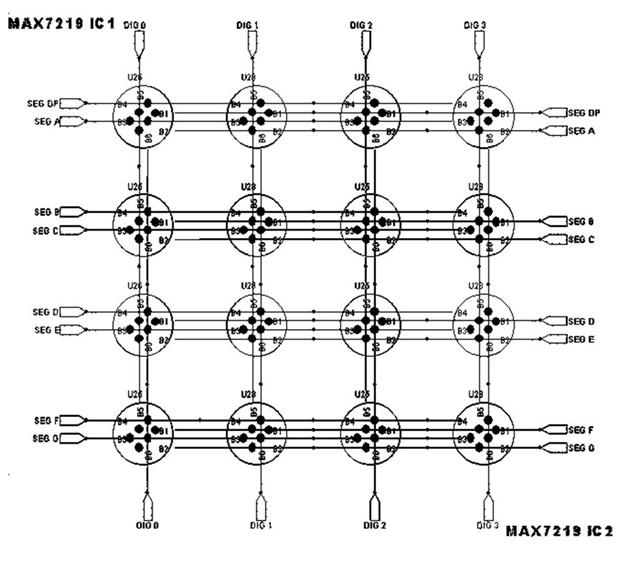
Figure 6 Led Array
3.2 USB Interface
Hardware
Requirements:
o
PIC18F4550
o
20MHz Crystal
oscillator
o
USB 2.0
o
USB Connector
o
Push buttons "Reset" and
"Program"
o
Resistors
o
Capacitors
o
Status LEDs
The Microchip® PIC18F4550 microcontroller is the heart of the board. It is a programmable microcontroller with 32Kbytes of flash program memory and 2Kbytes of general purpose SRAM. It has 13 A/D inputs making the system ideal for use in real-world monitoring applications and 18 general purpose I/O ports. There are 2 PWM channels, one 8-bit Timer and three 16-bit Timers. Auxiliary communication is provided by RS232 Communication (1 Channel), USB Communication (1 Channel), SPI (3-wire SPI Module), I²C (with Master/Slave Mode). This PIC is provided with boot loader which enables self programming (Self-Programmable under Software Control) of the PIC. It has the following Universal Serial Bus features:
• USB V2.0 Compliant
• Low Speed (1.5 Mb/s) and Full Speed (12 Mb/s)
• Supports Control, Interrupt, Isochronous and Bulk Transfers
• Supports up to 32 Endpoints (16 bidirectional)
• 1-Kbyte Dual Access RAM for USB
• On-Chip USB Transceiver with On-Chip Voltage
It has a Flexible Oscillator
Structure with following features:
• Four Crystal modes, including High Precision PLL for USB
• Two External Clock modes, up to 48 MHz
• Internal Oscillator Block:
- 8 user-selectable frequencies, from 31 kHz to 8 MHz
- User-tunable to compensate for frequency drift
• Secondary Oscillator using Timer1 @ 32 kHz
• Dual Oscillator options allow microcontroller and USB module to run at different clock
speeds
• Fail-Safe Clock Monitor:
Allows for safe shutdown if
any clock stops
PIC18F4550 PINOUT
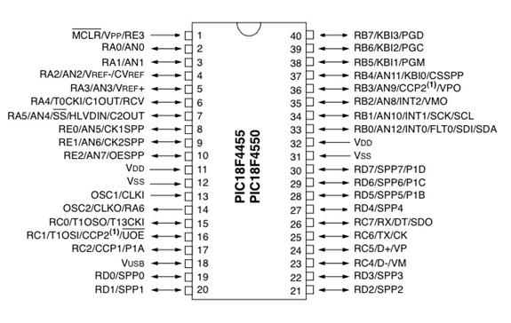
Figure 7 PIC18F4550 Pin out
It has
high-current sink/source of 25 mA/25 mA. There are three external interrupts.
Four Timer modules (Timer0 to Timer3) are present. It has a C Compiler
Optimized Architecture with Extended Instruction Set.
Specifications
Voltage on any pin with respect to VSS - -0.3V to (VDD + 0.3V)
Voltage on VDD with respect to VSS - -0.3V to +7.5V
Total power dissipation
- 1.0W
Maximum current out of VSS pin -
300 mA
Maximum current into VDD pin -
250 mA
Maximum output current sunk by any I/O pin -
25 mA
Maximum output current sourced by any I/O pin -
25 mA
Maximum current sunk by all ports - 200 mA
Maximum current sourced by all ports - 200
mA
The crystal oscillator is used to provide
the clock for the PIC. A crystal oscillator has a very stable Q. It is
equivalent to an LCR circuit. It oscillates at its resonating frequency. Here
the crystal provides 20 MHz clock to the PIC. It requires resistors and
capacitors to oscillate properly
Universal Serial Bus (USB) is a serial bus standard to interface . Its
features include providing power to low-consumption devices without the need
for an external power supply and allowing many devices to be used without
requiring manufacturer specific, individual device drivers to be installed. A USB cable has two wires for power (+5 volts and ground)
and a twisted pair of wires to carry the data.
USB supports
three data rates: A Low Speed (1.1, 2.0) rate of 1.5 Mbit/s (187.5 kB/s) that is mostly used for Human Interface Devices (HID)
such as keyboards, mice, and joysticks and a Full Speed (1.1, 2.0) rate of 12 Mbit/s (1.5 MB/s). Full Speed devices divide the USB bandwidth between
them in a first-come first-served basis and it is not uncommon to run out of
bandwidth with several isochronous devices. All USB Hubs
support Full Speed. A Hi-Speed
(2.0) rate of 480 Mbit/s (60 MB/s).
|
Pin
|
Name
|
Cable colour
|
Description
|
|
1
|
VCC
|
Red
|
+5V
|
|
2
|
D−
|
White
|
Data −
|
|
3
|
D+
|
Green
|
Data +
|
|
4
|
GND
|
Black
|
Ground
|
Figure 8 USB Pin Description
The USB standard uses "A" and "B" connectors to avoid confusion:
o
"A" connectors head "upstream" toward the computer.
o
"B" connectors head "downstream" and connect to
individual devices.
USB 2.0 has added higher maximum speed of 480 Mbit/s. The USB 2.0 specification
covers all three speeds 480 Mbps, 12 Mbps, and 1.5 Mbps. USB 2.0 (High-speed USB) provides additional
bandwidth for multimedia and storage applications and has a data transmission
speed 40 times faster than USB 1.1.
The USB Connector is a standard "type
B" connector. There are four connections in a USB cable, two of which
supply power while the other two are the communication lines D+ and D-. By
these pins information is transferred between the host computer and the
PIC when it is being programmed, and
while firmware sends or receives data with the computer if it is a HID
application.
Figure 9 USB CONNECTOR
The two
buttons are used during the process of programming the PIC. If the Reset button
is pushed while holding down the Program button, the PIC will enter the boot
loader mode, which will allow a new application to be loaded into the PIC. One
of the general purpose I/O pins is dedicated to the "program" button
to enter boot loading mode
The reset button is connecter to MCLR pin.
They show the
state of USB. The various conditions are shown below.
Figure 10 State LED Status
Design:
For providing the clock
using crystal oscillator 22pF capacitors and 1Mohm resistors are required. They
make the crystal oscillate properly. A capacitor 0.47μF is connected across the pin
18. It is required for the proper functioning of internal voltage regulator. A
decoupling capacitor of value 0.1μF is connected across the power pins of USB socket. Status
LEDs are connected at pins 19 and 20.
Figure 11 Schematic
of the USB interface
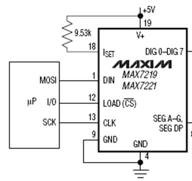
Figure 12 SCHEMATIC
OF LED DRIVER WITH PIC
The SPI interface
of the PIC 18f4550 is connected to the respective pins of the MAX 7219.
Figure 13 Basic block diagram of power
supply
Hardware
requirements:
o
A
Transformer (8-0-8V,1A)
o
Bridge
Rectifier (Power Diode BY127)
o
Regulator
IC 7805
o
Power
Transistor 2n2955
It steps down the input
230V, 50 Hz AC to 8-0-8 V, 1A.
The bridge rectifier provides full wave
rectification from a two wire AC input. It is formed of power diode
BY127. The ac input voltage is applied to the
diagonally opposite ends of the bridge. . The load resistance is connected
between the other two ends of the bridge. For the positive half cycle of the
input ac voltage, diodes D1 and D3 conduct, whereas diodes D2 and D4 remain in
the OFF state. The conducting diodes will be in series with the load resistance
RL and hence the load current flows through RL. For the
negative half cycle of the input ac voltage, diodes D2 and D4 conduct whereas,
D1 and D3 remain OFF. The conducting diodes D2 and D4 will be in series with
the load resistance RL and hence the current flows through RL
in the same direction as in the previous half cycle. Thus a bi-directional wave
is converted into a unidirectional wave.
The +5 volt power supply is based on the commercial 7805
voltage regulator IC. This IC contains all the circuitry needed to accept any
input voltage from 8 to 18 volts and produce a steady +5 volt output, accurate
to within 5% (0.25 volt). It also contains current-limiting circuitry and
thermal overload protection, so that the IC won't be damaged in case of
excessive load current; it will reduce its output voltage instead.
Specifications
|
Output Voltage
|
5V
|
|
Ripple rejection ratio
|
78dB
|
|
Input regulation
|
3mV
|
|
Load regulation
|
15mV
|
Figure 14 7805 Pinout
It is used to boost the output current.
Figure 15 Power Supply Circuit
The
bridge rectifier rectifies the ac input signal. This is being smoothened by the
capacitor C1, the output is regulated by IC 7805. A power transistor is
used to supply extra current to the load the regulator, maintaining a constant
voltage. Currents up to 650mA will flow through the regulator, above this
value and the power transistor will start to conduct, supplying the extra
current to the load. This should be on an adequate heat sink as it is likely to
get rather hot. For a 5v regulator 7805.
The input voltage should be a few volts higher to allow for voltage drops.
Assume 8 volts. Assume that the load
will draw 5amps. The power dissipation in the transistor will be Vce * Ic
or (8-5)*5=15watt.
The
software used for circuit design is EAGLE. The program consists of three main
modules: Layout Editor, Schematic Editor, Auto router which is embedded in a
single user interface. Therefore there is no need for converting net lists
between schematics and layouts. Its General
features are:
Ø online Forward- and Back-Annotation
Ø context sensitive help function
Ø no hardware copy protection
Ø multiple windows for board, schematic and library
Ø powerful User Language
Ø integrated text editor
Ø available for Windows und Linux
Layout Editor has following features
Ø maximum drawing area 1.6 x 1.6m (64 x 64 inch)
Ø resolution 1/10,000mm (0.1 micron)
Ø up to 16 signal layers
Ø conventional and SMT parts
Ø comes with a full set of part libraries
Ø easily create your own parts with the fully integrated
library editor
Ø undo/redo function for ANY editing command, to any depth
Ø script files for batch command execution
Ø copper pouring
Ø cut and paste function for copying entire sections of a
drawing
Ø design rule check
Schematic Editor provides the
following features
Ø up
to 99 sheets in one schematic
Ø electrical
rule check
Ø gate-
and pin swap
Ø create
a board from a schematic with a single command
The PCB design
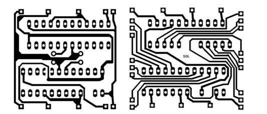
comprises of three sections:
It
is a double sided PCB with the upper side of PCB comprising of the anode lines
of the LEDs .the cathode lines are laid on the bottom side of the PCB. The
anode lines are horizontal lines. The cathode lines are vertical lines.![cleardot[1]](final report_files/image032.gif) The track width is 10 mils. ((for 1A
current). circular pads has been laid with diameter of pad 0.5 mm greater than
hole diameter. Pads are laid for nodes
on the top side and holes for cathodes and vice versa.
The track width is 10 mils. ((for 1A
current). circular pads has been laid with diameter of pad 0.5 mm greater than
hole diameter. Pads are laid for nodes
on the top side and holes for cathodes and vice versa.
Tracks have angles
of 45 degree or so (never 90 degree).
PCB for led array


 This
is designed as two layers PCB. The tracks never end at 90 degrees the VCC
tracks (20 mils) are having greater width than normal tracks. The ground tracks
are of width 40mils
This
is designed as two layers PCB. The tracks never end at 90 degrees the VCC
tracks (20 mils) are having greater width than normal tracks. The ground tracks
are of width 40mils
Led driver PCB
This is single sided PCB with provisions
for reset and program buttons and USB connector. The foot prints of PIC, resistors,
capacitors were provide by the software
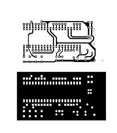
Figure 18 Microcontroller PCB
|
|
|
|
|
 |
|
|
|
SEND THE INCOMING
DATA TO 7219 VIA SPI.
|
|
The software used to send data is written in Visual C++ 6.0
#include <stdio.h>
#include "windows.h"
#include "mpusbapi.h" // MPUSBAPI Header File
//---------------------------------------------------------------------------
// Global Vars
char vid_pid[]= "vid_04d8&pid_000c"; // Default Demo Application Firmware
char out_pipe[]= "\\MCHP_EP1";
char in_pipe[]= "\\MCHP_EP1";
DWORD temp;
HINSTANCE libHandle;
HANDLE myOutPipe;
HANDLE myInPipe;
//---------------------------------------------------------------------------
// Prototypes
void GetSummary(void);
void LoadDLL(void);
void GetUSBDemoFWVersion(void);
DWORD SendReceivePacket(BYTE *SendData, DWORD SendLength, BYTE
*ReceiveData,
DWORD
*ReceiveLength, UINT SendDelay, UINT ReceiveDelay);
void CheckInvalidHandle(void);
//Custom Functions
void Raw7219(BYTE addr,BYTE data);
void LoadHigh();
int SendString(BYTE *send_buf,BYTE len);
void MakeRGBMap(BYTE *map, char *string);
#include "io_cfg.h"
#include "usb.h"
int main(int argc, char* argv[])
{
if(argc <= 2)
{
printf("\r\n-
USAGE : mdb.exe <id><len><string>");
return 1;
}
BOOLEAN bQuit;
DWORD selection=7;
bQuit = false;
// Load DLL when it is
necessary, i.e. on start-up!
LoadDLL();
LoadMap();
setRGB[0][0]=&setR1Col;
setRGB[0][1]=&setR2Col;
setRGB[0][2]=&setR3Col;
setRGB[0][3]=&setR4Col;
setRGB[1][0]=&setG1Col;
setRGB[1][1]=&setG2Col;
setRGB[1][2]=&setG3Col;
setRGB[1][3]=&setG4Col;
setRGB[2][0]=&setB1Col;
setRGB[2][1]=&setB2Col;
setRGB[2][2]=&setB3Col;
setRGB[2][3]=&setB4Col;
// Always a good idea to
initialize the handles
myOutPipe = myInPipe =
INVALID_HANDLE_VALUE;
int i,j;
BYTE color,rg_b,b_b;
char string[23];
printf("Enter the
string to be displayed : ");
gets(string);
printf("Enter the
color : \n");
printf(" 1. Red
\n");
printf(" 2. Green
\n");
printf(" 4. Blue
\n");
printf(" : > ");
scanf("%d",
&color);
printf("Displaying %s
with colour %d ",string,color);
printf("RG,B
Brightness [0-15] : ");
scanf("%d%d",&rg_b,&b_b);
//g_b=b_b=15;
//strcpy(string,"11");
//string[1]=255;
//string[1]='+';
//string[1]=0;
BYTE send_buf[64];
const int num_boards = 8;
int offset=0;
//color=7;
while(1)
{
//for(string[0]='A';string[0]<='Z';string[0]++,color++)
{
i=0;
color%=8;
if(!color)color=1;
//ClearBuffer(send_buf,64);
ClearAll7219();
BYTE
ic1=0,ic2=num_boards>>1;
int k=0,p=offset;
while(string[i])
{
while(map[string[i]][k?k-1:0])
{
if(ic2 ==
32)goto EOI;
if(p
>= 0)
{
(*setRGB[0][(p)%4])(ic1,ic2,(color
& 1)?map[string[i]][k]:0);
(*setRGB[1][(p)%4])(ic1,ic2,(color
& 2)?map[string[i]][k]:0);
(*setRGB[2][(p)%4])(ic1,ic2,(color
& 4)?map[string[i]][k]:0);
if(p
&& p%4==0)
{
ic1++;
ic2++;
}
}
k++;
p++;
}
i++;
k=0;
}
EOI:
{
InitMax7219(num_boards,send_buf,rg_b,b_b);
for(j=0;j<4;j++)
{
Shift7219(offset-1);
for(int
n=0;n<num_boards;n++)
{
if(num_boards-n-1
== 4)
max[num_boards-n-1].exportByteInverse(j,send_buf+2+4*n);
else
if((num_boards-n-1 == 5) || (num_boards-n-1 == 6))
max[num_boards-n-1].exportByteHalfInverse(j,send_buf+2+4*n);
else
max[num_boards-n-1].exportByte(j,send_buf+2+4*n);
}
SendString(send_buf,num_boards*4);
}
Sleep(300);
//offset--;
}
//for(i=2;i<2+32;i++)
// printf("%02x ",send_buf[i]);
//printf("\n");
} }
// Always check to close
all handles before exiting!
if (myOutPipe !=
INVALID_HANDLE_VALUE) MPUSBClose(myOutPipe);
if (myInPipe !=
INVALID_HANDLE_VALUE) MPUSBClose(myInPipe);
myOutPipe = myInPipe =
INVALID_HANDLE_VALUE;
// Always check to close the
library too.
if (libHandle != NULL)
FreeLibrary(libHandle);
return 0;
}//end main
The custom firmware code for translating the data from the Universal Serial Bus
(USB) to SPI for MAX7219
#include <p18cxxx.h>
#include <usart.h>
#include <delays.h>
#include "system\typedefs.h"
#include "system\usb\usb.h"
#include "io_cfg.h"
// I/O pin mapping
#include "user\user.h"
#include <spi.h>
/** V A R I A B L E S
********************************************************/
#pragma udata
byte counter;
byte trf_state;
DATA_PACKET dataPacket;
/** P R I V A T E P R O T O T Y P
E S ***************************************/
void BlinkUSBStatus(void);
void ServiceRequests(void);
void InitMAX7219(void);
void SendRaw7219Packet(void);
void OutSerialData(void);
/** D E C L A R A T I O N S **************************************************/
#pragma code
void UserInit(void)
{
mInitAllLEDs();
InitMAX7219();
}//end UserInit
/******************************************************************************
* Function: void ProcessIO(void)
*
* PreCondition: None
*
* Input: None
*
* Output: None
*
* Side Effects: None
*
* Overview: This function is a place holder for
other user routines.
* It is a mixture of both USB
and non-USB tasks.
*
* Note: None
*****************************************************************************/
void ProcessIO(void)
{
BlinkUSBStatus();
// User Application USB tasks
if((usb_device_state <
CONFIGURED_STATE)||(UCONbits.SUSPND==1)) return;
ServiceRequests();
}//end ProcessIO
void ServiceRequests(void)
{
byte index;
if(USBGenRead((byte*)&dataPacket,sizeof(dataPacket)))
{
counter = 0;
switch(dataPacket.CMD)
{
case READ_VERSION:
//dataPacket._byte[1] is len
dataPacket._byte[2] = MINOR_VERSION;
dataPacket._byte[3] = MAJOR_VERSION;
counter=0x04;
break;
case
RAW_MAX_PACKET://RAW_MAX_PACKET
SendRaw7219Packet();
dataPacket._byte[2]
= ~dataPacket._byte[2];
dataPacket._byte[3]
= ~dataPacket._byte[3];
counter=0x06;
break;
case
OUT_SERIAL_DATA:
OutSerialData();
LOAD7219
= 1;
dataPacket._byte[1]=0x02;
dataPacket._byte[2]=dataPacket._byte[0];
counter=0x03;
break;
case
PULSE_LOAD:
LOAD7219
= 1;
break;
case RESET:
Reset();
break;
default:
break;
}//end switch()
if(counter != 0)
{
if(!mUSBGenTxIsBusy())
USBGenWrite((byte*)&dataPacket,counter);
}//end if
}//end if
}//end ServiceRequests
/******************************************************************************
* Function: void InitMAX7219(void)
*
* PreCondition: None
*
* Input: None
*
* Output: None
*
* Side Effects: None
*
* Overview: Initializes the SPI port for MAX7219
*
*
* Note:
*
*
*****************************************************************************/
void InitMAX7219(void)
{
TRISCbits.TRISC7 = 0; //
Enabling SPI Pins Master mode
TRISBbits.TRISB1 = 0;
OpenSPI(SPI_FOSC_64,
MODE_00, SMPEND);
tris_LOAD7219 =
OUTPUT_PIN;
LOAD7219 = 0;
}//end InitMAX7219
void SendRaw7219Packet()
{
LOAD7219 = 0;
WriteSPI(dataPacket._byte[2]);
WriteSPI(dataPacket._byte[3]);
dataPacket._byte[4]=0x55;
dataPacket._byte[5]=0xAA;
LOAD7219 = 1;
counter = 0xff;
while(counter--);
}
void OutSerialData()
{
byte index;
//dataPacket.data[DATA_SIZE-1]
= 0; // Precaution null terminator
LOAD7219 = 0;
index = 0;
counter = dataPacket.len;
while(index<counter)
{
WriteSPI(dataPacket.data[index]);
index++;
}
}
/******************************************************************************
* Function: void BlinkUSBStatus(void)
*
* PreCondition: None
*
* Input: None
*
* Output: None
*
* Side Effects: None
*
* Overview: BlinkUSBStatus turns on and off LEDs
corresponding to
* the USB device state.
*
* Note: mLED macros can be found in
io_cfg.h
* usb_device_state is declared
in usbmmap.c and is modified
* in usbdrv.c, usbctrltrf.c,
and usb9.c
*****************************************************************************/
void BlinkUSBStatus(void)
{
static word led_count=0;
if(led_count == 0)led_count =
10000U;
led_count--;
#define mLED_Both_Off() {mLED_1_Off();mLED_2_Off();}
#define mLED_Both_On() {mLED_1_On();mLED_2_On();}
#define mLED_Only_1_On() {mLED_1_On();mLED_2_Off();}
#define mLED_Only_2_On() {mLED_1_Off();mLED_2_On();}
if(UCONbits.SUSPND == 1)
{
if(led_count==0)
{
mLED_1_Toggle();
mLED_2 = mLED_1; // Both blink at the same time
}//end if
}
else
{
if(usb_device_state ==
DETACHED_STATE)
{
mLED_Both_Off();
}
else if(usb_device_state
== ATTACHED_STATE)
{
mLED_Both_On();
}
else if(usb_device_state
== POWERED_STATE)
{
mLED_Only_1_On();
}
else if(usb_device_state
== DEFAULT_STATE)
{
mLED_Only_2_On();
}
else if(usb_device_state
== ADDRESS_STATE)
{
if(led_count == 0)
{
mLED_1_Toggle();
mLED_2_Off();
}//end if
}
else if(usb_device_state
== CONFIGURED_STATE)
{
if(led_count==0)
{
mLED_1_Toggle();
mLED_2 =
!mLED_1; // Alternate blink
}//end if
}//end if(...)
}//end if(UCONbits.SUSPND...)
}//end BlinkUSBStatus
Ø
Program
to drive the LED driver MAX 7219 has been obtained.
Ø
LED
matrix has been implemented
Ø
The
program for USB Interface has been run successfully
Ø
The USB
Interface has been implemented
Ø
The LED
Matrix could be developed for video display. Each LED represents a pixel. By
the intense packing of LEDs video display is possible.
Ø
The wireless LED board could be developed. GSM
and GPRS based Designs are Public utility products for mass communication. This
is a Scrolling (Moving) Message Electronic Display Board which displays the
messages received as SMS or GPRS Packets.
Datasheets referred :
°
MAX7219
°
PIC18F4550
°
PIC16F84A
°
TLC5940A
°
RGB LED
Websites
referred:
www.microchip.com
www.ti.com
www.maxim-ic.com
All the
information present in this document and further information is available at
rgb.kitiyo.com
Appendix
Figure 19 Cost Report
|
ITEM
|
COST
PER UNIT(RS)
|
UNITS
|
TOTAL
(RS)
|
|
RGB
LED
|
10
|
128
|
1280
|
|
PIC
18F4550
|
FREE SAMPLE
|
|
|
|
LED driver
MAX 7219
|
FREE SAMPLE
|
|
|
|
PCB
|
|
|
500
|
|
Misc
Components
|
|
|
220
|
|
TOTAL
|
|
|
2000
|
° MAX7219
° PIC 18F4550